ArchiCAD Tutorial | ArchiCAD Virtual Trace: A Versatile Catalyst for BIM
bу Eric Bobrow, March 20, 2008
Originally Published in AECbytes Tips and Tricks Issue #28
In ArchiCAD 11, Graphisoft introduced Virtual Trace™, a powerful ground-breaking technology. Similar in concept to the architect’s familiar trace paper, it allows any drawing or view to be overlaid on top of or beside any other view. This digital light-table is amazingly versatile, and can be used in a large variety of contexts to simplify coordination of information and speed up the design process. Moreover, it can be a revolutionary catalyst, since it facilitates various hybrid 2D / 3D workflows which can ease the transition from 2D CAD to 3D BIM (Building Information Modeling), both inside the office and with consultants.
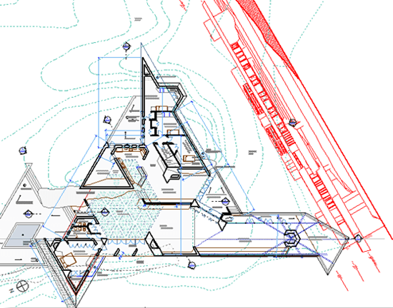
A simple use of Virtual Trace is to overlay the floor plan from one story over another one in the same project (similar to the Ghost Story feature of previous ArchiCAD versions). This allows a designer to examine and refine the relationship of the elements between the stories, making sure walls are stacked or aligned properly, as well as mechanical systems and structure. For example, the image below shows the first floor in light blue as Virtual Trace Reference under the second floor.
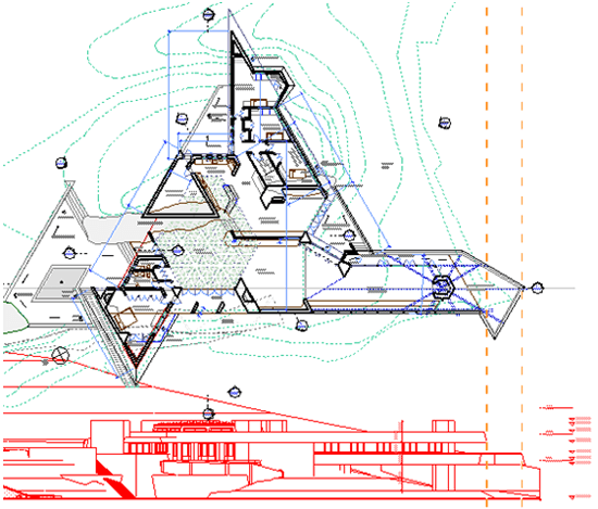
However, Virtual Trace goes much further than Ghost Stories. For example, it allows an elevation or a section to be viewed next to a floor plan, or two elevations or sections next to each other in the same window. This is far more powerful than seeing these two related views in separate windows (as in all other BIM applications), as one can use the reference as an editing aid to align, snap, measure or pick up settings from elements in the traced view. The image below shows a Plan view with an Elevation as Trace Reference—note the dashed guidelines from the Elevation drawing that help to align elements from two different stories.
One can quickly switch back and forth to edit two related views, and see the floor plan immediately update when changing an elevation drawing. Working on a live view of the project, such as a plan or elevation, one can see and coordinate with the layout sheet on which it is placed. Virtual Trace makes it simple to align drawings on one sheet to corresponding drawings on another sheet.
The dynamic Visual Compare features within the Virtual Trace palette give many options for analyzing relationships and differences between two drawings, whether they are:
- two related floor plans
- earlier and later versions of a design
- before and after views of a remodel
- a consultant’s drawing being coordinated with the architect’s work
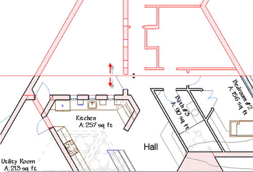
An example of coordinating consultants’ work is shown in the image below, where a structural DWG is used as Trace Reference under the floor plan, isolated in the upper half with the Splitter.
Interactively varying the opacity or placement of either drawing helps the eye to see subtle relationships, as does the splitter which can slide across the screen to reveal one drawing against the other. Differences that might have been missed because of the complexity of graphic information are easily spotted and can be redlined or noted for action.
Unlike some BIM programs, ArchiCAD has always allowed a flexible process, never insisting that “everything be done in 3D.” Whenever desired, the 3D model information can be manipulated in 2D to create beautiful, precisely controlled drawings.
With Virtual Trace, this hybrid workflow (in which the 3D model informs and coordinates the 2D documents) is even more easily managed. This is a revolutionary catalyst that will allow firms of any size to transition at their own pace from 2D CAD to 3D BIM.
Virtual Trace Basics
We’ll start with a basic introduction to activating and controlling Virtual Trace. For a more detailed explanation of all the interface options, please refer to the ArchiCAD 11 Reference Manual, pages 117 – 125.
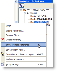
The simplest way to activate Virtual Trace is to right-click in the Project Map on the desired Story, Section or Elevation and choose Show as Trace Reference.
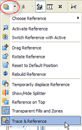
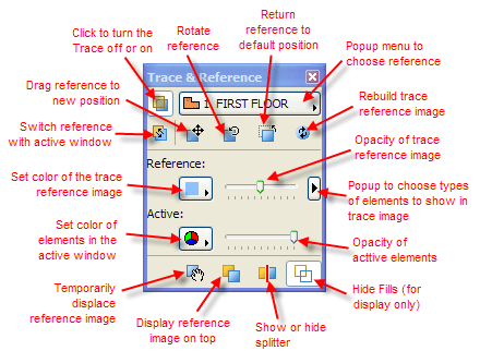
The Trace Reference can be controlled by commands in the Trace & Reference popup menu located in the Toolbar.
It is much easier to interactively control these features by using the Trace & Reference floating palette. As highlighted above, select Trace & Reference from the popup menu to open this elegant and compact palette. You can see the different options of the Trace & Reference palette in the image below.
When a Trace Reference is shown, it is seen inside the active editing window, with the contents under or beside those in the active view. While one may snap to or pick up settings from the Reference elements, they may not be selected or edited while being seen as a Trace. If you try to select or edit an element from a trace reference, a message will say “This element is inactive in this view.”
The colors of the Reference and Active elements can be set as desired using popup menus, either as single colors or using their original pen colors. The sliders for the Reference and Active drawings change the opacity or visual density of the images. To simplify what is shown in the reference drawing for legibility, use the popup in the middle of the right side to turn off categories such as dimensions, text, or fills.
The Trace can be turned off or on with a single click of the top left button, and dragged, rotated, returned to a default position or rebuilt (refreshed or updated) with buttons underneath the top popup menu that choose among recent reference views. Clicking the Switch button near the top left will make the current reference view active, and set the current active view to be the trace reference.
The Visual Compare controls at the bottom of the palette simplify study of the trace reference. One can move it temporarily aside, bring it on top of the active elements, split the window with sliders that reveal one image against the other, or make fills transparent to show elements otherwise hidden.
The best way to learn the effect of each of these controls is simply to try them out. They are quick (and even fun) to test, and easy to understand. In addition, Graphisoft has created some interesting video demonstrations of Virtual Trace at http://www.graphisoft.com/products/archicad/ac11/action/ .
TIP: One can select a View from the View Map to act as a Trace Reference, or select an entry in the Project Map. Be careful though—if you reference a View with different layers turned on than your active window, ArchiCAD will have to work harder to calculate and display two different layer “conditions,” which may slow down your redraw and navigation. Whenever possible, choose a Reference from the Project Map that will then show that viewpoint using the same layers as the active window.
Versatility Galore
The applications for Virtual Trace are almost endless. In BCG’s classes for users upgrading to ArchiCAD 11, we regularly spend more than two hours exploring various ways that it can be used, without exhausting the possibilities.
Here are some of the ways in which Virtual Trace can be applied:
- Overlaying one story against another to verify structural relationships, or to snap and align new elements in relation to those on the traced story.
- Showing the site plan or a lower story as a light image underneath another floor plan—this can be printed for study or presentation.
- Seeing a plan overlaid with another view of the same story which has different layers turned on (such as cabinets, structure or landscaping).
- Developing a site plan in a 2D Worksheet while coordinating with the building model.
- Viewing and aligning elements to an elevation or section while working on the floor plan, as shown below (note that the elevation will automatically rotate as needed to align next to the plan drawing).
- Working on an elevation or section while studying the floor plan of any of the related stories (the floor plan will automatically rotate to align properly to the elevation).
- Drawing or modeling in one elevation or section while comparing, snapping or picking up settings from another elevation or section side by side (these will automatically align to each other vertically).
- Editing an elevation while seeing a section that is “further back” directly behind it.
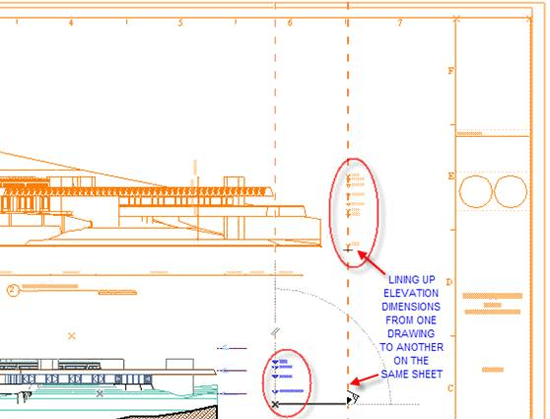
- Working on dimensioning or other annotation of a drawing while seeing the sheet on which it is placed (along with other drawings on that layout), or with a blank sheet image to visualize how it will look on paper.
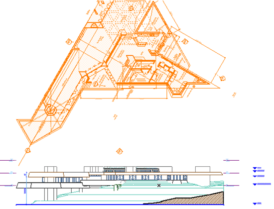
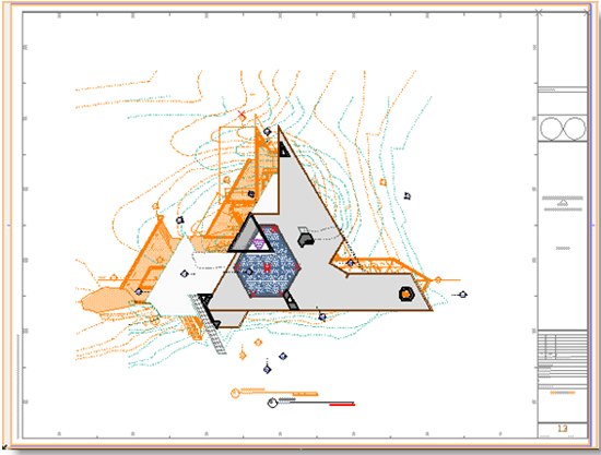
- Adjusting the placement of drawings on a layout while viewing another sheet underneath (see illustration below of Roof Plan layout with Floor Plan sheet as reference in orange underneath).
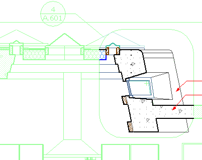
- Editing a detail drawing while seeing the original context from which it is called out, as shown below—this is particularly important if the model has been modified.
- Coordinating any enlarged 2D drawing (such as a restroom plan or a wall section) in a Worksheet against the latest version of the “live” model from which it was excerpted.
- Examining a DWG file from a consultant to see how it relates to the architectural drawing, to shop drawings or to other consultants.
- Reviewing one version of a drawing against an earlier one.
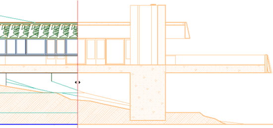
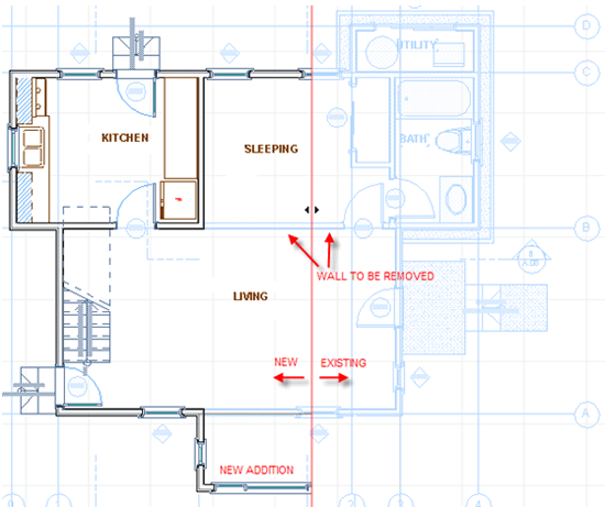
- Comparing new designs versus the as-built or existing building, as shown below, where the Splitter reveals the existing drawing as a trace reference, with the “active” new addition on the left.
- Maintaining consistency and accuracy of manually drawn or edited sections, elevations or interior elevations against the latest version of the 3D model (see final section of this article for more comments on this).
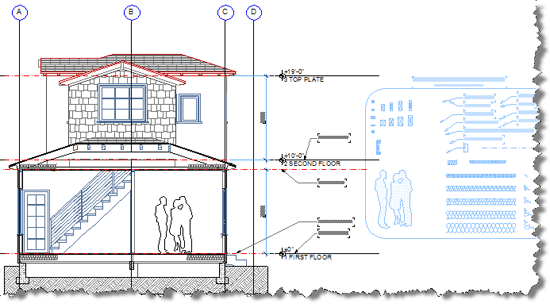
- Picking up element settings with the eye-dropper from an interactive legend of visual favorites shown as a trace beside the active working view (see illustration below from BCG’s ArchiCAD MasterTemplate).
TIP: Each viewpoint in the Project Map will remember the last 5 Trace References that were used. These may be accessed from the popup menu at the top of the Trace & Reference palette. Certain viewpoints are automatically added to this list: for example, when viewing a plan, there are choices for one story up, one story down, and previous story (the last one you were looking at); or when viewing an interior elevation, the other interior elevations in that room will be available for quick reference.
Easing the Transition to BIM while Enhancing the Workflow
Graphisoft’s Virtual Trace technology can actually revolutionize the workflow in an office, while simplifying the transition to Building Information Modeling. Now all team members can participate actively in the BIM environment even if their skills or focus are primarily 2D. In addition, drawings from consultants can be coordinated more easily without requiring them to jump to a full BIM process.
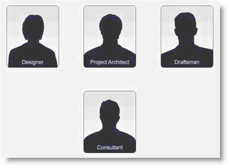
Let’s take a look at new possibilities in the workflow and relationships between team members inside an office as well as between architect and consultant. The image below depicts four distinct roles, each of which could be played by more than one person.
The Project Architect is of course the main designer and decision maker. In this scenario, he/she is comfortable with creating the design in 3D as a BIM model.
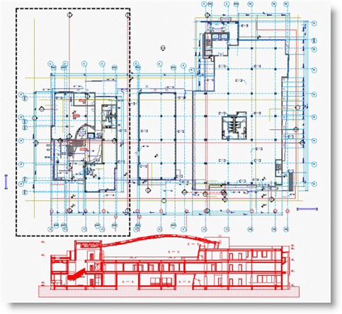
The first example involves the Design Workflow, in which the Project Architect is paired with a Designer who is much more proficient in 2D CAD than he/she is in 3D BIM. In ArchiCAD, the Designer can effectively develop the floor plan in a way quite similar to the traditional 2D CAD process, refining the space plan, program and detailing the structure. With Virtual Trace, he/she can easily see the relationship of the plan with the section as he/she makes changes, without having to become a “power modeler.” See the image below showing a plan with area in “marquee” ready to be adjusted, seen with a section below as trace reference.
Virtual Trace also improves the Coordination Workflow between the Project Architect and the Consultant. In the next example image, the structural drawing has been overlaid on top of the architectural plan, and the right-hand splitter has pulled back one drawing midway, to reveal plainly the differences next to door D124. Notice how the walls in red from one drawing do not properly line up with the walls in black from the other drawing. Even though the consultant may work in traditional 2D CAD, the DWG information can be coordinated effortlessly in ArchiCAD’s Virtual Building.
Virtual Trace also enhances the Documentation Workflow between the Project Architect and the Draftsperson, helping greatly in the creation of high quality documentation. Virtual Trace allows you to keep the 3D model “live” for coordination purposes even in the late phase of the detailed construction documentation.
In our final example, the model section remains “live” while the draftsperson edits a copy of it to create the detailed section. If the design changes, for example the story height needs to be changed, it is very easy to update the detailed section through coordination with the model. In this image, part of one drawing is pulled back with the splitter. Notice how the upper story does not match the revised model, while the lower story still overlays cleanly.
The draftsperson can edit the final section drawing in a 2D worksheet without having to touch the model, while seeing and aligning precisely with the model as a trace reference.
Graphisoft has prepared a fascinating short video clip that vividly illustrates these examples, and their potential impact on the roles and workflow in an architectural office. Please visit http://www.graphisoft.com/products/archicad/ac11/ and click on the graphic link near the top of the page “Virtual Building & Virtual Trace.”


