ArchiCAD Tutorial | ArchiCAD Office Standards and Templates
bу Eric Bobrow, June 1, 2008
Originally published in AECbytes Tips and Tricks Issue #30
Office standards set the graphic appearance and organization of documents produced by a firm. They also play a significant role in promoting consistency, efficiency and usability of the project files and workflow. A key ingredient in making standards work is to embed them into template files that are used to start projects.
ArchiCAD has a special file type called a template or TPL file. When one uses a TPL file to start a project, ArchiCAD makes an untitled copy. When saving the project the first time, a prompt asks for a name and location for the project file, which prevents inadvertently overwriting the template file itself.
It is common for template files to be empty shells, akin to blank sheets of paper, in which one builds the project. However, it is possible to set up templates containing a rich array of attributes, a pre-defined structure and useful reference materials.
This article will explore a number of different ways that template files can help simplify and speed up the workflow, as well as supporting office standards. ArchiCAD MasterTemplate (www.actemplate.com), a commercial product that my company has created, will be used as an example to show how far one can take this approach.
Building a Set of Construction Documents
In the simplest and broadest terms, the process that leads to construction documents using ArchiCAD (and to varying extents other CAD and BIM tools) focuses on four complementary, interlocking areas:
- Geometry
– The actual building design as embodied in its form and composition
- Drawings
– The representation and annotation of the design in a series of viewpoints from different orientations and levels of detail
- Attributes
– Graphic styles of representation including types of lines and fills
– Complex combinations of these such as composite walls, slabs and roofs
– Libraries of objects, doors, windows and markers
– Definitions of pens / lineweights and materials
– Organizational tools such as layers and layer combinations
- Structure
– The defined inter-relationship of drawings and layout sheets
– Definitions of views and hierarchies of related views in folders
– Setup of schedules to report quantities and tabulate data
– Master layouts that serve as title-block backgrounds for the sheets
Geometry, of course, is basic to our concept of building, and formal drawings date back at least several hundred years. Attributes and structure (in the way I use these terms) are more recent, part of the computerized representation of building designs.
When a new project file is started, although it is figuratively “a blank canvas,” two of these four areas are already present. There is no geometry (unless it is a remodel or addition), and thus no drawings to speak of. However, attributes and structure are already present—there are line types, layers, materials, and other basic attributes, and some views, layouts and master layouts may be defined.
A good template will set up ahead of time a robust set of attributes and an extensive structure, to facilitate creating the model and drawings according to office standards. Graphisoft supplies an ArchiCAD template with a basic structure and a standard set of attributes that is easy to understand and widely usable. This is what you get when you first install ArchiCAD and start up the program. You can return to it by choosing File > New and then selecting Use a Template > ArchiCAD 11 Template.
The original Graphisoft template provides default settings for all the tools so that when you activate any tool and start to draw, you get something common and reasonable for the country you live in. In the U.S., pick the Wall tool and without modifying any settings, you’ll get a 10′ wall that is 9″ thick; the Slab tool is pre-set to draw slabs that are 12″ thick with top surface set at 0. When you place a section or other type of marker, it is set for a marker commonly used in your area.
Defining Office Standards
Part of defining office standards is to examine the settings for these tools, and rework them as needed to achieve the graphic look you prefer. This may of course be based on previous standards, from another CAD package, or even paper drawings. A common way to establish standards is to work them out as you produce your first project, or over time while working on multiple projects. Careful examination of the plotted output, and some experimentation, will result in drawings that are clean, crisp and well balanced, with a style appropriate for your firm and type of projects.
Typical office standards specify the sizes of text and markers, the fonts used, the title block and sheet numbering system. Line types, weights and pen colors are set. In most CAD and BIM applications, layer naming and usage is also standardized. Wall types, other construction components, and symbols for objects, doors and windows are set up but may vary for each project.
Traditionally, office standards are codified and represented on paper. However, in a complex, sophisticated system such as ArchiCAD, it is useful to embed examples inside a project file since there are so many settings that need to be encompassed. A printed ArchiCAD Standards manual may show and describe the desired end result, but the best way to implement the standard is using tools within the software and project file.
Settings can be “remembered” using ArchiCAD’s Favorites palette (which can be opened using Window > Floating Palettes > Favorites). This palette allows a user to save one or more presets for each tool, which can be activated by simply double-clicking on the entry in the Favorites list. Use of Favorites is discussed in detail in my ArchiCAD article from December 2006.
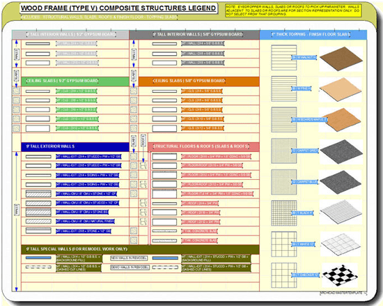
A complementary approach, also discussed in that article, is to set up an Interactive Legend of Visual Favorites. These arrays of elements may be samples of walls, slabs, roofs and other structural components, or examples of library parts (freestanding objects, or doors and windows placed into walls). By having them in a visual display or “Legend,” one can peruse and choose the most appropriate one, then pick up their settings using the eye-dropper (ALT or OPTION click).
Whether using Favorites or Interactive Legends, office standards (or project standard wall types, etc.) may be easily applied. A user will not have to spend time figuring out how to make the wall, window, dimension text, or other element have the right line weight, size, linetypes, layer, etc. Proper usage will reduce the common problem of inconsistent settings: e.g., some walls being drawn 4″ thick, others 4 ½” thick; objects being put on incorrect layers or pens; text being different sizes; etc.
In addition to preferred element settings (which mainly involve attributes), the structure of the file is an equally important part of office standards. This structure includes View definitions (including Model View Options) and how these Views are placed and numbered on layouts using Master Layouts in the Layout Book.
Creating a Template File
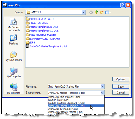
You can create a template file simply by saving a normal PLN file as a TPL file using File > Save As from the Floor Plan window. Choose ArchiCAD Project Template (*.tpl) from the file-type popup.
As a starting point, you might just take the basic ArchiCAD template supplied by Graphisoft, replace the generic title block in the Master Layout with the appropriate information for the firm, and be done with it.
You can also go to finished or well-developed projects, look for things that have been added or modified (such as layers, wall types, materials, Views, Layout numbering, etc.) and recreate them in the template file. You can use the Attribute Manager (go to Options > Element Attributes > Attribute Manager) to copy and paste attributes such as layers, materials or composites from one project to another. However, file structure as defined in the View Map and Layout Book will have to be recreated manually, since Attribute Manager does not deal with the Navigator structure.
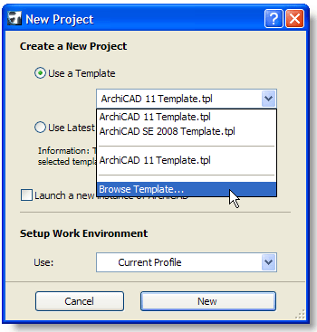
Once the file is ready, simply save as a TPL, then close it before starting a project. To start a project, choose the option when creating a new file to Use a Template, then browse for and select the TPL file. You’ll get an untitled project file that has all the attributes and structure from the TPL.
The next time you select Use a Template, that TPL file will be the default in the popup list of recently used template files, making it easy to use it again.
When you want to revise the template file itself, you’ll need to open it, rather than using it as a template. Use File > Open and navigate to find the TPL file.
NOTE: to select the TPL file in the Open File dialog box, you may need to change the file type popup to All Files or ArchiCAD Template files rather than ArchiCAD Solo Project files.
After opening the TPL file, you’ll see its name at the top of the window (whereas when you use the TPL file as a template, you’ll see Untitled at the top instead); you’ll then be able to make changes to the TPL file itself. After making changes, save the TPL and then close the file before using it for the next project startup.
Creating a Template from an Existing Project File
A great way to “remember” or recreate the preferred office standard structure is to start a project from a completed project that has a similar structure. One can simply “delete the building” and leave the structure (and attributes) behind, then start work on the new design.
This process (taking a completed project and gutting the building before starting work) can be done without using a template file. However, a template will make this simpler and easier, since deleting the building and unneeded parts of the file structure requires a number of steps. This also allows the office standards to develop over time, and the structure of the template to be enhanced.
Creating a template from an existing project file is straightforward:
1. Open a completed or well-developed project
2. Go to File > Save As, choose TPL file from the popup for file types.
a. Give it a descriptive name such as “Smith ArchiCAD Template.TPL.”
b. Store it in an easily accessible place with other reference materials, either on your server or your local hard drive. A good place for this might be inside the Jobs folder, in a folder for ArchiCAD Office Standards.
3. Delete the building and annotation:
a. Show and unlock all layers
b. Fit in Window to see the entire project (do this on the ground floor or whatever story has the furthest extents).
c. Use the Marquee tool to draw a “heavy” marquee around the entire project.
d. Hit the Delete key to erase the project contents.
– You’ll get a warning about deleting source markers (such as sections, elevations, interior elevations and details). Hit the Cancel button—this will tell ArchiCAD to cancel deleting these source markers, but to go ahead and delete the rest of the info.
– If you wish, manually delete source markers that will not be useful for new projects; for example, detail marker and interior elevation callouts vary so much that you will want to delete all but one of each to use as a starting point for picking up settings.
– You can leave Detail windows in the file even if you delete the source marker, if they will be useful for future projects. They will become Independent Details, and can be linked to from new detail markers later.
e. Go through the Project Map and review each Elevation, Section, Interior Elevation, Worksheet, and Detail window, and delete any that will not be useful in the next project. Open up each window that remains, and delete any 2D annotation that is not generally relevant.
– In sections or elevations, you may leave common labels, notes or symbols. That way, when annotating the next project, these just have to be moved into position or edited rather than starting from scratch.
– If you leave some 2D elements in these windows, move them to the side and organize them a bit so they’ll be easier to work with.
– Again, if you delete a detail marker that is the source for a Detail window, you have the choice to retain that drawing as an Independent Detail that can be referenced in future projects.
4. Save the file again—it should remain as a TPL rather than a PLN. Close the file.
When you start a project based on this more elaborate template, you’ll have a lot of structure already set up. Of course, you’ll need to make adjustments. Review the story settings and set them up for the appropriate heights and number of stories. Move the Elevation and Section markers as needed for the new building design. Then proceed to create your new project, and you’ll see how much further ahead you are. For example, the plans, sections and elevations are already laid out on the sheets, and just need to be updated when you’re ready to plot!
How Far Can One Go?
Over time, a template can be set up that has a more extensive and general structure and more “complete” set of attributes than any individual project. This will make it easier for a user to work on a range of project types, without necessarily having to find (or figure out) which previous project would be the best match (and thus the best starting point). However, some offices may find it useful to create more than one template file, perhaps for different types of projects (e.g., residential vs. commercial, or new vs. remodel).
Office standards embodied as Template files can have all sorts of conveniences built in, and can extend to supporting files such as Detail Libraries, new or customized library parts, and module (MOD) files with room layouts, complex assemblies, or Interactive Legends. The effort to create some of these elements and structures can be amortized over a number of projects, and added to over time. For firms that have a CAD or BIM manager, this can be part of the job description: “mining” successful projects for materials and approaches that can be reused.
My father Jack Bobrow worked for the Jet Propulsion Laboratories (JPL) in Pasadena from 1967 to 1983. He was called a Technology Utilization Specialist, and went around to JPL scientists working on various parts of the space program and other research projects. He interviewed them about innovations they made during that project, then wrote them up in a Tech Brief which NASA would distribute to other research labs. These ideas were reused or adapted to handle similar challenges by other teams.
Even if you work alone or in a small office, you can do the same thing: review what innovations and structure were created for each successful project, and see what can be reused in your template. Perhaps there are some great detail drawings that would apply to other projects; or a kitchen or bathroom design that might be a good starting point for other buildings. Are there wall types, materials, or special layer combinations and views that you created that could be used next time? Consider adding these to the TPL file, or another resource or reference file.
Any detail drawing you might use again should be added to your standard library of details. For an overview of ways to create and manage a detail library in ArchiCAD, please see my ArchiCAD article from May 2007. If a detail drawing is standard for many projects, you can leave it in the TPL file itself in an Independent Detail window, as well as pre-placed onto a standard detail sheet in the Layout Book.
The ArchiCAD MasterTemplate
Last year, our company (Bobrow Consulting Group, or BCG) created office standard templates for quite a few firms of different sizes. We aimed each time to optimize the files to take advantage of all that ArchiCAD 10 and later 11 had to offer. Of course, there was a lot these templates had in common.
BCG decided to undertake the ambitious task of creating the best possible template for ArchiCAD users: the ArchiCAD MasterTemplate. With the luxury of unlimited resources (that’s not really true, but we certainly weren’t constrained in the same way as any of our clients) and a lot of experience (18 years of ArchiCAD for me and 12 years by architect Scott Bulmer), we tackled the project. Several hundred hours later, we have versions of MasterTemplate for ArchiCAD 10, 11, Start Edition, and both U.S. and international metric editions.
This article is not the proper forum for describing MasterTemplate in detail—for that you can visit www.actemplate.com. However, I’d like to describe some of the approaches we took that may inspire our readers towards useful development of their own template and office standard files.
MasterTemplate has lots of Layers, Layer Combinations, Model View Options and Views. We took a lot of time to carefully rename and organize them to be easier to scan and navigate. We use these enhanced attributes and structure for lots of different purposes.
Layer combos can do more than just define what goes onto each drawing: they can optimize many different parts of the design workflow. Different layer combos are set up for sitework, massing, detailed design of the whole building, interior furnishings, and for creating detail drawings with Interactive Legends as smart kits of 2D parts.
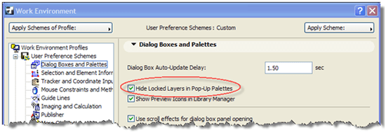
Each layer combination is set up with all hidden layers also being locked. This ensures that (with the proper preference set in Options > Work Environment > Dialog Boxes and Palettes, as shown below) only a short list of Layers is shown whenever the Layer popup palette is used, even though there are a lot of layers in the project.
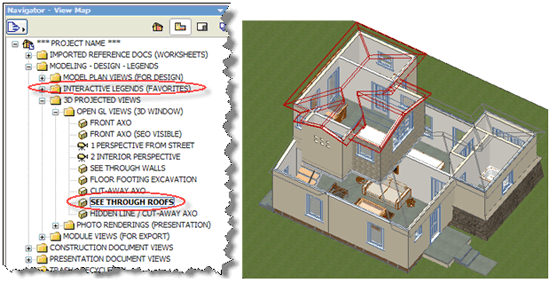
In a similar way, Views in the View Map define more than just the Drawings that will go on the Layout sheets. Specialized Views are set up to jump to the Interactive Legends of Visual Favorites, giving quick access to the office standard walls, windows, doors, furniture and other elements. There are also preset views for various 3D angles and display options—some of my favorites use layer combos that turn the roofs or walls into wireframe, so that one can see into the building for presentations and study.
Clone folders (see my ArchiCAD article from November 2007) are set up in MasterTemplate to automatically create more Views as needed, with all the right settings. That way, as more sections are drawn, or more interior elevations, etc., there are always Views ready to be edited and placed onto Layouts.
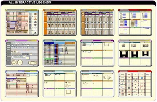
The Interactive Legends of Visual Favorites are an area we spent a lot of time developing. They are comprised of a number of groups of elements, with each group organized in a legend panel. These panels are carefully sized to keep the text readable when viewed as a whole onscreen. One can use the eye-dropper to pick up the settings of a desired element, then return to the building and place or draw the element.
Each panel focuses on related groups of elements, such as walls and other composite structures, doors, windows, objects, room layouts, etc. The legends are extensible so that users may add to them as they wish.
These legends are maintained in a separate Hotlinked MOD file for two reasons. This allows them to be updated throughout the office from one location. It also allows the legends to be turned off instantly by hiding the Master Layer of the Hotlinked Module. That way the legend elements are not seen in 3D views, elevations or sections, even though these elements are on the same layers as the building design itself.
In MasterTemplate, the Layout Book is structured for two different project types: a small project with sequential sheet numbering (A.01 through A.15), and a larger structure divided into subsets (e.g. A300 series for Plans, A400 series for Elevations, etc.). One can simply use the appropriate set of sheets, and discard the others.
Many pieces of boilerplate text are pulled from File > Info > Project Info, so one can simply fill in the Project Info (or have an administrative person do it) and the sheets will have that data already entered. Since Project Info can be saved to an XML file and loaded from the XML, this data can be carried from one project to another very easily.
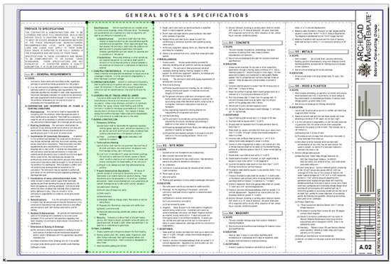
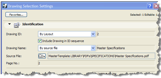
The general notes and specifications for the project are set up ahead of time linked to a PDF file. The notes are prepared in Word, with a custom page size matching the columns on the layout sheet, one page equaling one column. When the Word document is saved as a PDF, the layout sheets receive the updated contents. This way, the specs can be written and maintained in the word processor and there is virtually no time spent getting them onto the sheets.
Many of the Layouts have Drawings already pre-placed on the sheets. With a robust template, you can focus on designing and making a 3D model for your project, annotate it, and the views are already laid out for plotting. In fact, in one dramatic demonstration, I took an entire building model from a different project file, and pasted it into the ArchiCAD MasterTemplate file. When I went to the Layout Book and asked it to update the drawings, the plans, sections and elevations were pretty much all laid out ready to go.
The ArchiCAD MasterTemplate is an example of how far one can go with a template system. Any firm can develop its own template, and refine it over time to become more powerful. It just takes time and effort, like all good things in life!
Conclusions
The success of a firm is partly dependent on creating, developing, maintaining and using office standards well. Template files can embed these standards and make them easy to apply.
By using ArchiCAD’s built-in concept of a TPL file, one can build up a rich framework from which to produce consistent work in an efficient and effective manner. Best practices can take a physical form in the structure of the template. Embodying the office standards helps them to be visible, tangible and something that can be continually improved.
To give me feedback or ask questions about this article, please send an email to article@bobrow.com. I look forward to hearing from you!


